
rastertek강좌에서 소개하는 프러스텀 컬링 기법이 의미하는 수학적 해석
안녕하세요! 이번에 rastertek강좌에서 소개하는 프러스텀 컬링기법에 사용된 수학적인 해석을 토론해보는 시간을 가져보도록하겠습니다.
저가 프러스텀컬링 기법을 검색해보니 많은 자료가 나왔는데, 그 중에서 이 기법에 관하여 rastertek강좌를 번역및 편집해주시는분이 보이지 않더라구요. 그래서 한번 포스팅올려봅니다.
우선 rastertek강좌를 보다오신분은 해당 링크에서 공부해오셨는지 확인해주시기 바랍니다.
http://www.rastertek.com/dx11tut16.html
Tutorial 16: Frustum Culling
Tutorial 16: Frustum Culling The three dimensional viewing area on the screen where everything is drawn to is called the viewing frustum. Everything that is inside the frustum will be rendered to the screen by the video card. Everything that is outside of
www.rastertek.com
이 강좌에서는 보시다시피 절두체영역에 해당하는 오브젝트만을 선별하여 GPU연산을 실행하도록 하는 최적화 기법인 프러스텀 컬링을 소개합니다.
그 중 해당 강좌에서 쓰인 프러스텀 컬링부분입니다.
void FrustumClass::ConstructFrustum(float screenDepth, D3DXMATRIX projectionMatrix, D3DXMATRIX viewMatrix)
{
	float zMinimum, r;
	D3DXMATRIX matrix;


	// Calculate the minimum Z distance in the frustum.
	zMinimum = -projectionMatrix._43 / projectionMatrix._33;
	r = screenDepth / (screenDepth - zMinimum);
	projectionMatrix._33 = r;
	projectionMatrix._43 = -r * zMinimum;

	// Create the frustum matrix from the view matrix and updated projection matrix.
	D3DXMatrixMultiply(&matrix, &viewMatrix, &projectionMatrix);

	// Calculate near plane of frustum.
	m_planes[0].a = matrix._14 + matrix._13;
	m_planes[0].b = matrix._24 + matrix._23;
	m_planes[0].c = matrix._34 + matrix._33;
	m_planes[0].d = matrix._44 + matrix._43;
	D3DXPlaneNormalize(&m_planes[0], &m_planes[0]);

	// Calculate far plane of frustum.
	m_planes[1].a = matrix._14 - matrix._13;
	m_planes[1].b = matrix._24 - matrix._23;
	m_planes[1].c = matrix._34 - matrix._33;
	m_planes[1].d = matrix._44 - matrix._43;
	D3DXPlaneNormalize(&m_planes[1], &m_planes[1]);

	// Calculate left plane of frustum.
	m_planes[2].a = matrix._14 + matrix._11;
	m_planes[2].b = matrix._24 + matrix._21;
	m_planes[2].c = matrix._34 + matrix._31;
	m_planes[2].d = matrix._44 + matrix._41;
	D3DXPlaneNormalize(&m_planes[2], &m_planes[2]);

	// Calculate right plane of frustum.
	m_planes[3].a = matrix._14 - matrix._11;
	m_planes[3].b = matrix._24 - matrix._21;
	m_planes[3].c = matrix._34 - matrix._31;
	m_planes[3].d = matrix._44 - matrix._41;
	D3DXPlaneNormalize(&m_planes[3], &m_planes[3]);

	// Calculate top plane of frustum.
	m_planes[4].a = matrix._14 - matrix._12;
	m_planes[4].b = matrix._24 - matrix._22;
	m_planes[4].c = matrix._34 - matrix._32;
	m_planes[4].d = matrix._44 - matrix._42;
	D3DXPlaneNormalize(&m_planes[4], &m_planes[4]);

	// Calculate bottom plane of frustum.
	m_planes[5].a = matrix._14 + matrix._12;
	m_planes[5].b = matrix._24 + matrix._22;
	m_planes[5].c = matrix._34 + matrix._32;
	m_planes[5].d = matrix._44 + matrix._42;
	D3DXPlaneNormalize(&m_planes[5], &m_planes[5]);

	return;
}
흠... 우선 코드만으로 보면은 왜 이렇게 짰는지 알수없습니다.
당장 rastertek사이트가서 봐도 크게 자세히는 설명되어있지 않죠.
ConstructFrustum is called every frame by the GraphicsClass.
It passes in the the depth of the screen, the projection matrix, and the view matrix.
We then use these input variables to calculate the matrix of the view frustum at that frame.
With the new frustum matrix we then calculate the six planes that form the view frustum.
이게 끝입니다.
그러면 왜 이렇게 구현되었는지 수학적으로 해석해보도록 하겠습니다.
투영행렬 유도과정
r -> aspect ratio: 종횡비
a -> field of view: 수직시야각
n -> near: 프러스텀에서 제일 가까운 점
f -> far: 프러스텀에서 제일 먼 점
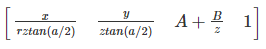
우선 투영행렬은 다음과 같이 생겼습니다.

우선 해당 식에서는 A와 B가 쓰였는데, A와 B는 각각 z좌표를 [-1, 1]구간으로 일반화하는데 사용됩니다.
이랬을때 동차좌표가 1인 [x, y, z, 1]이라는 임의의 정점을 곱한다면 다음과 같이 나옵니다.
그다음 여기서 동차나누기를 하면 다음과 같이 나옵니다.
우선 다들 아시다시피 DirectX11은 상향벡터(Up Vector)가 y축인 xz평면좌표계잖아요?
따라서 깊이버퍼링알고리즘을 수행하기 위해서는 z축으로 일반화를 해야할 필요가있습니다.
z축은 [0, 1]구간으로 일반화됩니다.
따라서 구간[n, f]를 구간[0, 1]로 사상(Mapping)하기 위해서는 f(z)라는 함수가 필요합니다.

우선 두가지경우로 나뉩니다.
1. if n에서 0으로 사상하는 경우
B에 대하여 정리해보면

해당 식에서만 본래함수 f를 f로하고 다른식에서의 far을 가리키는 f는 far로 했습니다.
헷갈리지않도록.
이렇게 나오고,
2. if f에서 1로 사상하는 경우
A에 대하여 정리해보면

그러면 최종적으로 B도 이렇게 연립해서 계산해보면
B는 이렇게 나옵니다.

따라서 우리가 원하는 투영행렬의 최종 모양은 이렇게 생기게 되죠.

소스코드 설명
// Calculate the minimum Z distance in the frustum.
zMinimum = -projectionMatrix._43 / projectionMatrix._33;
r = screenDepth / (screenDepth - zMinimum);
projectionMatrix._33 = r;
projectionMatrix._43 = -r * zMinimum;
이 부분은 위에서 설명한 투영행렬에서의 절두체에서 가장 가까운 점을 의미하는 n을 구한뒤 A와 B를 적용하는 과정입니다.
이때 zMinimum이 n을 의미하구요. r이 A를 의미합니다.
먼저 zMinimum(n)을 구하는 식을 그대로 수학적공식으로 치환해보겠습니다.

하지만 우리는 DirectX의 초기화공정에서 뷰포트를 생성할때 사용했던 그 화면의 최대깊이가 프러스텀의 최대깊이입니다.
따라서 f(프러스텀에서 제일 먼 점)는 그냥 그대로 screenDepth변수를 통해 적용해준것입니다.
참고로 D3DXMatrix의 행렬의 행과 열의 표현은 다음과 같습니다.
Matrix._(y방향 1부터시작)(x방향 1부터시작)
다음은 행렬의 곱셈부분인데요.
// Create the frustum matrix from the view matrix and updated projection matrix.
D3DXMatrixMultiply(&matrix, &viewMatrix, &projectionMatrix);
viewMatrix와 우리가 지금까지 구해준 투영행렬을 곱하는이유는 카메라, 즉 절두체에 대한 위치나 기하학적인 정보에 접근하기 위해서입니다. viewMatrix는 카메라에 대한 기하학적정보를 담고있는 행렬이기때문이죠.
각 평면의 법선벡터 구하기
마지막으로 각 행렬의 요소들을 계산하면서 일반화하는 구간입니다.
    // Calculate near plane of frustum.
	m_planes[0].a = matrix._14 + matrix._13;
	m_planes[0].b = matrix._24 + matrix._23;
	m_planes[0].c = matrix._34 + matrix._33;
	m_planes[0].d = matrix._44 + matrix._43;
	D3DXPlaneNormalize(&m_planes[0], &m_planes[0]);

	// Calculate far plane of frustum.
	m_planes[1].a = matrix._14 - matrix._13;
	m_planes[1].b = matrix._24 - matrix._23;
	m_planes[1].c = matrix._34 - matrix._33;
	m_planes[1].d = matrix._44 - matrix._43;
	D3DXPlaneNormalize(&m_planes[1], &m_planes[1]);

	// Calculate left plane of frustum.
	m_planes[2].a = matrix._14 + matrix._11;
	m_planes[2].b = matrix._24 + matrix._21;
	m_planes[2].c = matrix._34 + matrix._31;
	m_planes[2].d = matrix._44 + matrix._41;
	D3DXPlaneNormalize(&m_planes[2], &m_planes[2]);

	// Calculate right plane of frustum.
	m_planes[3].a = matrix._14 - matrix._11;
	m_planes[3].b = matrix._24 - matrix._21;
	m_planes[3].c = matrix._34 - matrix._31;
	m_planes[3].d = matrix._44 - matrix._41;
	D3DXPlaneNormalize(&m_planes[3], &m_planes[3]);

	// Calculate top plane of frustum.
	m_planes[4].a = matrix._14 - matrix._12;
	m_planes[4].b = matrix._24 - matrix._22;
	m_planes[4].c = matrix._34 - matrix._32;
	m_planes[4].d = matrix._44 - matrix._42;
	D3DXPlaneNormalize(&m_planes[4], &m_planes[4]);

	// Calculate bottom plane of frustum.
	m_planes[5].a = matrix._14 + matrix._12;
	m_planes[5].b = matrix._24 + matrix._22;
	m_planes[5].c = matrix._34 + matrix._32;
	m_planes[5].d = matrix._44 + matrix._42;
	D3DXPlaneNormalize(&m_planes[5], &m_planes[5]);
이 부분은 우선 우리가 앞에서 구한 뷰행렬과 투영행렬의 곱행렬인 matrix행렬변수와 프러스텀의 각 평면이 프러스텀 안쪽을 가리키는 법선벡터의 동차좌표곱으로 구할수있습니다.
우선 우리가 이번에 구할 평면의 법선벡터는 각각 (m_plane[n].a, m_plane[n].b, m_plane[n].c) 로 구성되며 그 사이의 거리는 d로 정의합니다.
여기서부터는 한 2주일? 3주일? 후에 작성한 글이라서 위의 글과 문맥이 안맞을 수 있는점 양해바랍니다.
우리는 이제 프러스텀평면의 abcd는 평면의 안쪽을 가리키는 방향벡터의 동차좌표와 행렬의 곱으로 구할 수 있습니다.

우리가 사용할 평면좌표계가 상향벡터가 y인 xz평면이라는 전제하에 진행하겠습니다.
평면의 안쪽을 가리키는 방향벡터들은 각각 이렇게 정의됩니다.
(위 그림에서 abcd가 동차좌표의 각 xyzw입니다.)
far plane: (0, 0, -1, 1)
near plane: (0, 0, 1, 1)
top plane: (0, -1, 0, 1)
bottom plane: (0, 1, 0, 1)
left plane: (1, 0, 0, 1)
right plane: (-1, 0, 0, 1)
따라서 우리는 최종적으로 프러스텀 평면의 각 법선벡터와 평면방정식을 통해 어떠한 점, 또는 기하구조등이 프러스텀안에 존재되어있는지 확인할 수 있게됩니다.
bool FrustumClass::CheckPoint(float x, float y, float z)
{
	int i;

	for(i=0; i<6; i++)
	{
		if(D3DXPlaneDotCoord(&m_planes[i], &D3DXVECTOR3(x, y, z)) < 0.0f)
		{
			return false;
		}
	}

	return true;
}
끝!
'🕹️자체엔진 > DirectX 11 개인공부' 카테고리의 다른 글
| Domain Shader로 구현하는 GPU기반 Deferred Shading Sphere Lighting Volume 코드 리뷰 [[ HLSL (0) | 2025.04.11 |
|---|---|
| DirectX11 공부 7주차. 멀티 텍스쳐링과 텍스쳐 배열 (0) | 2022.03.18 |
| DirectX11 공부 6주차. 폰트 엔진, DirectInput (0) | 2021.11.27 |
| DirectX11 공부 5주차. 2D모델 렌더링 (0) | 2021.11.20 |
| DirectX11 공부 4주차. 정반사광, 인스턴싱 (2) | 2021.11.17 |
댓글